If you consider only the static forces then indeed the thickness might seem over-engineered. However, engine blocks are not statically loaded. They operate in the range of a few hundred to a few thousand rpm (Revolution Per Minute), so there are dynamic considerations here.
Fatigue
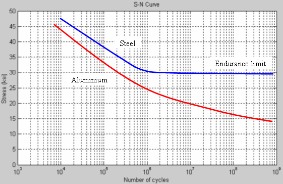
When materials are subjected to cyclic loading they exhibit a reduction in the allowable stresses. See below for an example:
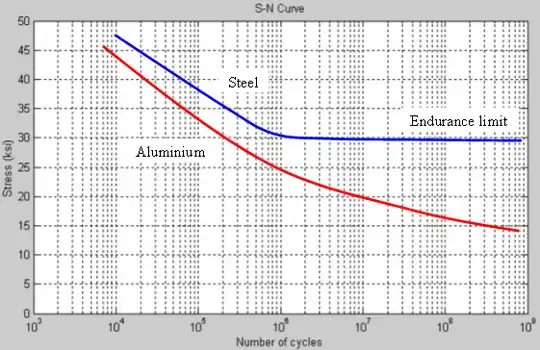
In general, BCC (body-centered cubic) materials (like steel) show a marked drop in strength (close to 50% or more depending on the steel). For these material there is stress (called the endurance limit), for which the material can be loaded indefinitely.
Also, FCC (face-centered cubic) materials (like aluminium) exhibit a very bad fatigue behaviour.
In any case, when there is high number of cyclic loads (like in the case of motor engine), the allowable stress tends to fall quite a lot. Therefore, there is a need to increase the cross-sections/thicknesses in order to reduce operating loads.
Just for giving an order of magnitude: an engine operating at 4000rpm, performs 1 million revolutions in little over 4 hours of continuous operation.
Vibrational Considerations
A second reason, has to do with vibrations. More specifically how to avoid having the engine operating in a frequency region that magnifies vibrations.
I'm sure everybody must have noticed at some point that, when an engine drops below certain rpms it starts to vibrate quite considerably. This is because it is in a frequency region near resonance.
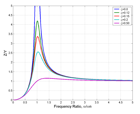
In the following image you can see the magnification factor for different damping ratios ($\zeta$) and frequency ratios ($r=\frac{\omega}{\omega_n}$). $\omega_n$ is the natural frequency. If the excitation frequency (i.e. rpm) is close to $\omega_n$ then vibrations tend to magnify (see Tacoma Narrows bridge).
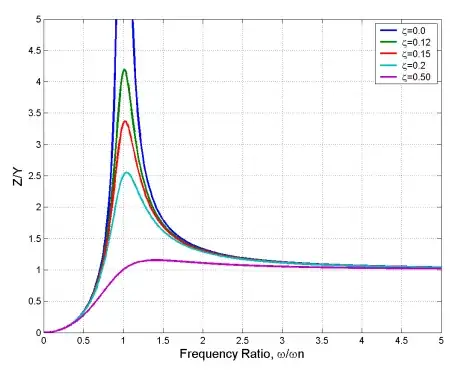
Although, it would be best if engines worked at a frequency ratio $r= {\omega \over \omega_n}$ which is close to zero, for many reasons its not feasible. So most engines opt to operate in a region close to $r>1.5$, so that the magnification factor is closer to 1. (This means that the amplitude of the vibration is approximately equal to the static deflection).
In order to do so they have to make sure that the operation is at $r>1.5$, they need to make sure that at the lowest operating rpm of a car (lets assume 750rpm$\approx 78.5 \frac{rad}{s}$) is greater than $\omega_n$ by at least 50%. (i.e. $\omega_n$ should be in the order of 50-55 rad/s).
The (simplified to a SDOF system) equation to calculate the $\omega_n$ is
$$\omega_n=\sqrt{\frac{k}{m}}$$
where:
- k is the stiffness of the supports (not that this is not the stiffness of the structure)
- m is the mass of the engine block.
So in order to reduce the natural frequency, they need to increase the mass. By decreasing the natural frequency, the frequency ratio becomes higher. Therefore, added mass that can be used for increasing the stiffness of the structure (not the supports), also has the added benefit that it moves the engine operation away from the resonance range.