1

EDIT: I will state my test problem description and then my solution. But before that, I would like to apprise you of the absence of the actual description given during test (which happened in Zoom and there I was provided with the link leading to tasks).

Problem 1. I was given a beam (that you may see below added as a picture from my textbook) and assigned to draw diagrams of internal forces ($Q$, $N$, $M$) which are shear force, axial (normal) force and bending moment. My question is how you know immediately that these diagrams are drawn incorrectly if all subconditions such as "differential identities" and "all equilibrium equations" hold true. Otherwise, I miss something and do not realise about this.

enter image description here

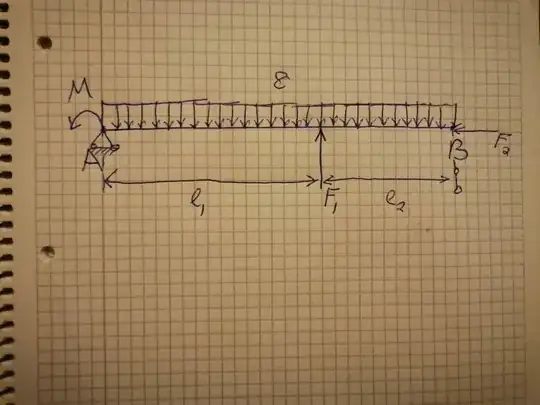
Here you might see a beam whose endings are A and B. At them, there are supports (at A it is non moving, so there arises two reactions, and at B it is moving, so leaving me with one reaction). The data is as follows: $q = 12 \frac{kN}{m} $, $M = 8 kNm$, $F_1 = 5 kN$, $F_2 = 14 kN$, $l_1 = 2.6 m$ and $l_2 = 1.2$, so $l = l_1 + l_2 = 3.8 m$.

First step is to solve reactions, for which I must compose equations of equilibrium:

$$ \sum_n F_n ^x = 0 \Rightarrow X_A - F_2 = 0 \Rightarrow X_A = 14 kN $$

$$\sum_n M_y ^A (F_n) = 0 \Rightarrow M + F_1 \cdot l_1 + l \cdot Z_B - q \cdot l \cdot \frac{l}{2} = 0 \Rightarrow Z_B \approx 17.27$$

$$\sum_n M_y ^B (F_n) = 0 \Rightarrow M - F_1 \cdot l_2 + q \cdot l \cdot \frac{l}{2} - Z_A \cdot l = 0 \Rightarrow Z_A \approx 23.33 kN$$

Notice that:

$$\sum_n F_n ^z = 0 \Rightarrow ql - Z_A - Z_B - F_1 \equiv 0$$

So, these reactions are correctly found and the equilibrium is maintained. Next, we are going to draw diagrams of internal forces. Here I am not going to be idle and show you my actions, so you would help me:

enter image description here

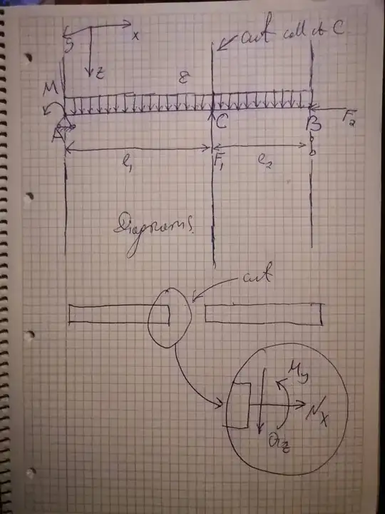
Idea is shown above on the pictures. Let us begin. The cut comes to the point C or to the part of the beam at C. Thus, we must consider two parts of the beams.

The part AC where $0 \le x \le l_1$. Internal forces are determined with equilibrium equations, so

$$\sum_n F_n ^z = 0 \Rightarrow Q_z + ql - Z_A - Z_B - F_1 = 0 \Rightarrow Q_z = 23.33 - 12x$$

Note that $l = x$ along the segment according to method of cut, sections. Next,

$$\sum_n M_y ^C (F_n) = 0 \Rightarrow M_y + M - Z_A \cdot x + q \cdot x \cdot \frac{x}{2} = 0 \Rightarrow M_y = 23.33x - 6x^2 - 8$$

$$\sum_n F_n ^x = 0 \Rightarrow X_A + N_x = 0 \Rightarrow N_x = - 14 kN$$

Note that the following equations are true:

$$\frac{\partial M_y}{\partial x} = Q_z, \\ \frac{\partial Q_z}{\partial x} = - q$$

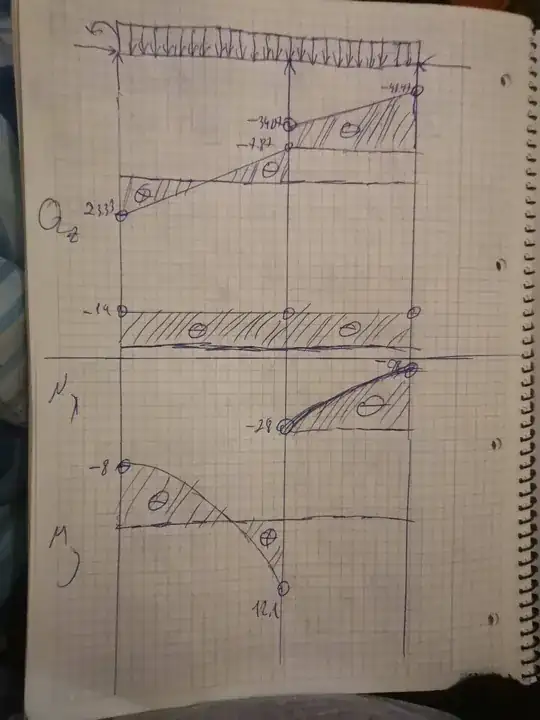
Thus, internal forces are found correctly and the equilibrium at the cut is maintained. Let us compute the internal forces' values at endings of the cut:

$$M_y (0) = - 8 kNm, \ M_y (2.6) = 12.098 kNm \\ Q_z (0) = 23.33 kN, \ Q_z (2.6) = - 7.87 kN$$

The second part is CB where $ 2.6 \le x \le 3.8$. Internal forces:

$$\sum_n M_y ^B (F_n) = 0 \Rightarrow M_y + M - Z_A \cdot (x + 2.6)- F_1 \cdot x + q \cdot (x + 2.6) \cdot \frac{x + 2.6}{2} = 0 \Rightarrow M_y = - 6x^2 - 2.87x + 20.098$$

Hence,

$$Q_z = \frac{\partial M_y}{\partial x} = - 12x - 2.87$$

The axial force is the same because on the cut there is no force $F_2$, because it is cut off. Again we compute values of internal forces and draw our diagrams:

enter image description here

The second problem was much harder. I had to do the same things but in that time, I was to determine the distribution load $q$, which they denoted by $p$. I had to draw diagrams of internal forces. In addition to that, I was provided with I-beam whose dimensions were given. I guess that this I-beam was given to make me compute the polar moment of the figure and use some formulae from strength materials theory to find such values of $q$ for which the beam is stable. That is the point. Technically, I drew incorrect diagram. But numbers are correct, so I drew incorrectly and compute correctly :)

1 Answers1

0

In such exercises, I suggest doing things by steps.

Your work goes from the equilibrium equations directly to the internal force equations. Instead, I suggest doing one thing at a time. The equilibrium equations give you the reactions, so let's make it clear what those are:

$$\begin{align} \sum F_x &= X_A - F_2 = 0 \\ \therefore X_A &= 14\text{ kN} \\ \sum F_y &= Y_A + Y_B + F_1 - q(\ell_1 + \ell_2) = 0 \\ \therefore Y_A + Y_B &= 40.6 \\ \sum M_A &= M + F_1\ell_1 + Y_B(\ell_1 + \ell_2) - \dfrac{q(\ell_1 + \ell_2)^2}{2} = 0 \\ \therefore Y_B &= \dfrac{\dfrac{q(\ell_1 + \ell_2)^2}{2} - M - F_1\ell_1}{\ell_1 + \ell_2} = 17.27\text{ kN} \\ \therefore Y_A &= 23.33\text{ kN} \end{align}$$

So, now that that is clear we can move on to the internal force diagrams.

Now, we can do this directly, as you seem to have tried to do, or explicitly by integration. To keep things clear, I'll use integration.

For the shear diagram, it's important to remember that there's a concentrated force, so there'll be a discontinuity.

$$\begin{align} Q(x) &= \int q(x) = qx + C \\ Q(0) &= C_{[0,2.6]} = 23.33 \\ Q(3.8) &= -12 \cdot 3.8 + C_{[2.6, 3.8]} = -17.27 \\ \therefore C_{[2.6, 3.8]} &= 28.33 \\ \therefore Q(x) &= \begin{cases} -12x + 23.33 & x \in [0, &2.6) \\ -12x + 28.33 & x \in (2.6, &3.8] \\ \end{cases} \\ \therefore Q(2.6^-) &= -7.87\text{ kN} \\ Q(2.6^+) &= -2.87\text{ kN} \\ \end{align}$$

So, what is different between this result and what you obtained? The values for $Q(0)$ and $Q(2.6^-)$ are right, but the first mistake we see is for $Q(2.6^+)$.

I don't understand how you got that result, but I assume you did it "intuitively", without performing explicit calculations for each segment of the beam. The correction then is to note that, when moving from left to right, a positive concentrated load leads to a positive change in shear force.

The way to remember this is by remembering the sign convention:

When moving from left to right, we are always looking at a beam element and looking at its left face (not the right face as you drew), where an upward vertical force means positive shear.

But the biggest red flag in your diagram is what you got at B. When calculating the reaction, you correctly obtained 17.27 kN, but your shear diagram at that point is -48.47 kN.

The fact that it's negative is correct, but it should be (in magnitude) equal to the reaction at B. This is because the reaction is upward and would therefore be a positive change to the shear, generating the expected zero shear to the (infinitesimal) right of B.

I can't quite understand your work to obtain the results to the right of $F_1$, so I can't quite point out what you did wrong,

And then we move to the bending moment, by integrating the shear diagram:

$$\begin{align} M &= \int Q(x) = \begin{cases} -6x^2 + 23.33x + C_{[0, 2.6]} &= 0 & x \in [0, &2.6) \\ -6x^2 + 28.33x + C_{[2.6, 3.8]} &= 0 & x \in (2.6, &3.8] \end{cases} \\ M(0) &= C_{[0, 2.6]} = -8 \\ M(3.8) &= -6 \cdot 3.8^2 + 28.33 \cdot 3.8 + C_{[2.6, 3.8]} = 0 \\ \therefore C_{[2.6, 3.8]} &= -21.01 \\ \therefore M &= \begin{cases} -6x^2 + 23.33x - 8 & x \in [0, &2.6) \\ -6x^2 + 28.33x - 21.01 & x \in (2.6, &3.8] \end{cases} \\ \end{align}$$

Once again, your results to the left of $F_1$ are correct (though the curvature of your curve is wrong, it should start a sharp drop and become flat near $F_1$, since the shear force is greatest at the support).

But then you have a discontinuity at $F_1$, which is obviously wrong: a discontinuity should only appear where there is a concentrated bending moment. A concentrated force causes a discontinuity in the shear diagram, but that simply means there's a discontinuity in the tangent of the bending moment.

And then, even more problematically, you have a non-zero moment at B, which is an edge simple support. As such, by definition, it should have zero bending moment.

And then to check our work:

enter image description here

enter image description here

enter image description here


Diagrams obtained via Ftool, a free educational 2D frame analysis tool.

Wasabi
  • 13,167
  • 8
  • 39
  • 62