5

I have no background in Mechanical Engineering.

It's intuitive to use an analogy as this guy demonstrated here @3:48 where he used caster wheels you would see in office chairs where the contact point is ahead of the wheel in relation to the direction of movement which causes the wheel to trail because of, presumably, the friction of the wheel to the ground resisting the movement which causes the wheel to lag behind which eventually causes it to self-center.

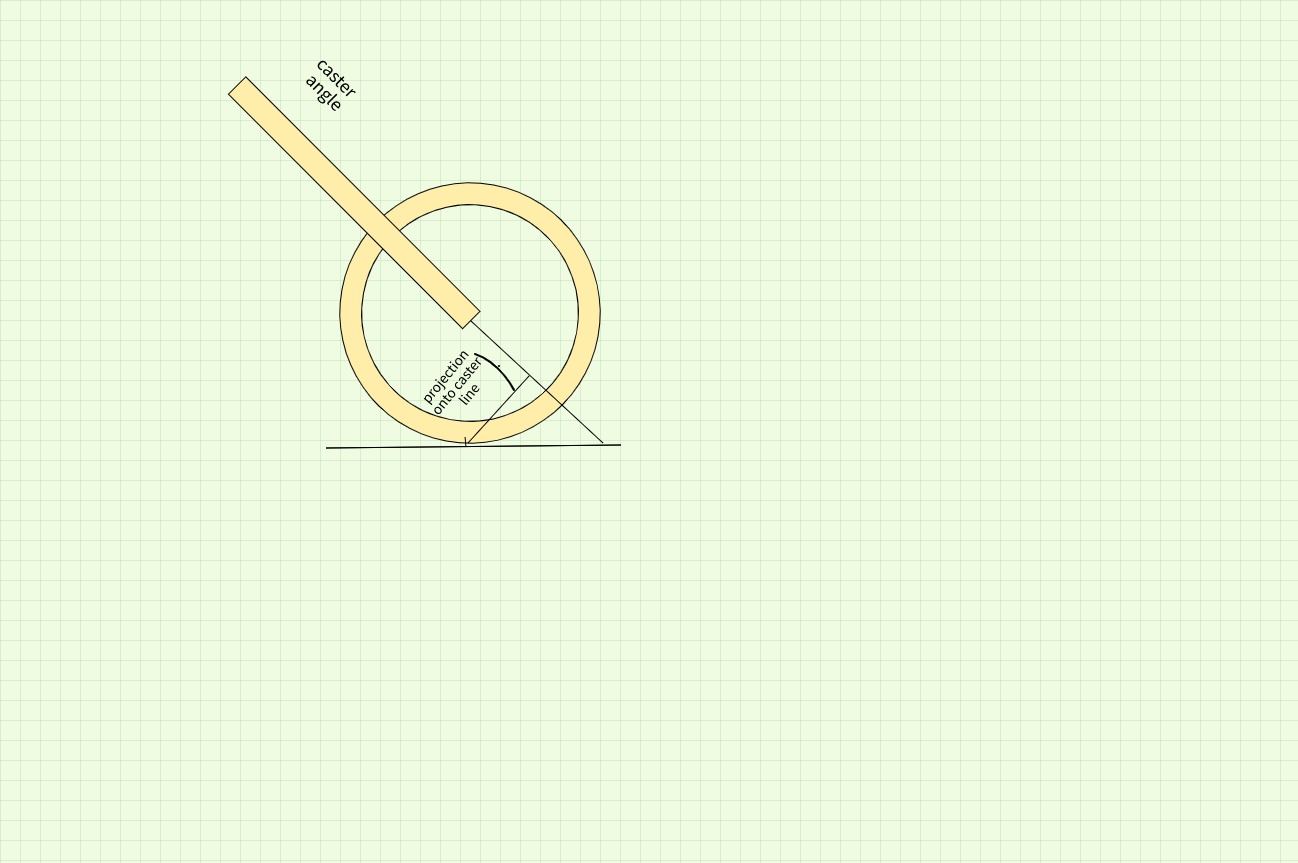
What I don't understand is how is caster wheels in an office chair analogy the same as caster angle describe in the following image and in this video?
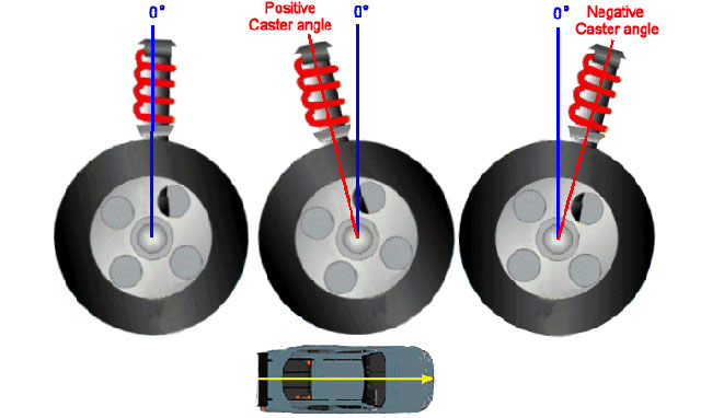
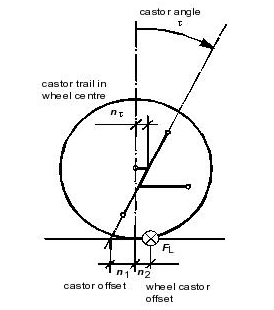
enter image description here

Fig. 1.

In the following image where the wheel is trailing the contact point above it (the rod) seems the exact opposite of the previous image where the the wheel is ahead of the contact point (the suspension).
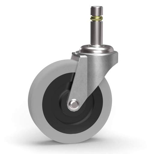
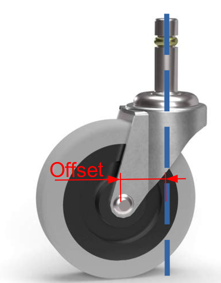
enter image description here

Fig. 2.

Update

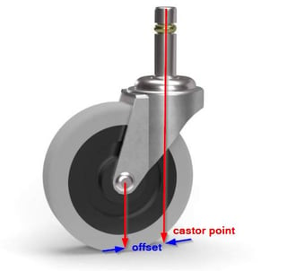
In an office chair or shopping cart wheel analogy, this is easier to understand as shown in the following illustration.
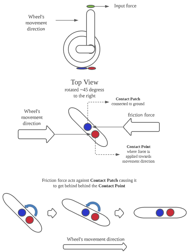
enter image description here

Fig. 3.

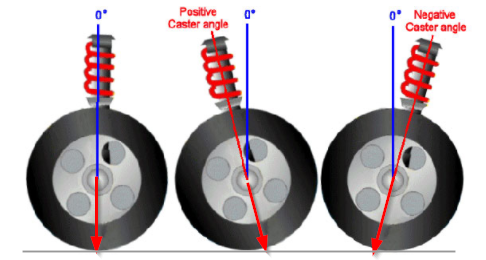
But as mentioned in @NMech's answer, the above illustrates wheel trailing the input force in the diagram which is different from caster angle shown below.
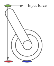
enter image description here

Fig. 4.

I am definitely missing something in that diagram I've made. My intuition sees only where the source of input is coming from whether it's behind the wheel or not determines if it's going to resist rotation or turn around. It's hard for me to see how rotational axis being behind the contact patch or not is going to have the same effect.

Transistor
  • 12,108
  • 2
  • 22
  • 32
supertonsky
  • 151
  • 4

3 Answers3

4

There are two different concepts there:

  • caster angle
  • caster trail at wheel center

enter image description here

enter image description here

Figure Caster offset

Both the angle and the offset are important to determine the castor offset and the castor point which is the important factor for the stability and self-centering of any wheel.


Edit: (light):

The idea is that you need to project the castor point, and apply the friction force on the contact patch. Then you need to calculate the moment with respect of the castor point.

NMech
  • 24,340
  • 3
  • 38
  • 77
3

enter image description here

Figure 1. The castor point is the intersection of the pivot axis with the floor.

enter image description here

Figure 2. For travel to the right we have three situations: (a) No castor action. (b) Correct castor action as the castor point is ahead of the point of contact of the wheel. (c) Reverse castor action which will be problematic in service.

What matters is where the axis of steering hits the road. For castor action that needs to be ahead of the point of contact between the wheel and the road.

Transistor
  • 12,108
  • 2
  • 22
  • 32
1

let's say the caster continues to the ground and intercepts the ground at x in front of the point the tire touches the ground.

The vertical force on the caster, F, and friction reaction on the tire creates a couple causing a torque, impeding the rolling of the wheel. the torqe is $F*x$

This torque turns the wheel until it lines up with the caster. And the torque is zero.

Edit

In response to OP's modified detail:

The moment arm producing the torque is not from the orange ellipse's vertical projection of the green input force in your diagram. It is the contact point "distance" from the axis of the caster. meaning we have to drop a vertical from the wheel's contact point to the extension of the caster, then project that distance on the ground. So it is steel the wheel following the driving force.

.

caster torque

kamran
  • 23,517
  • 2
  • 22
  • 42