3

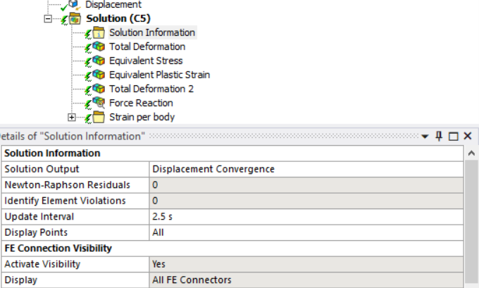
I am currently conducting a static structural analysis study in Ansys and encountered convergence prolems. I have a very large thermal gradient (almost 600°C) as input from a precedent transient thermal analysis which I apply gradually. I am looking to analyse thermally induced stresses. Large deformationas are turned on. enter image description here

The model constists only of shell elements which are connected by MPCs (defined as bonded and sticking according to solution output). I have fixed supports and I am making use of cyclic symmetry. So naturally, my model is over-constrained. Running static structural analysis with only mechanical loads and without thermal gradient converges quickly and without any problems.

The problem does not converge oncy I apply the thermal input. I already tried reducing time step sizes to a minimum of 0,001s (1/100 of time step). Reducing mesh sizing did not help convergence either and only steps up calculation time drastically.

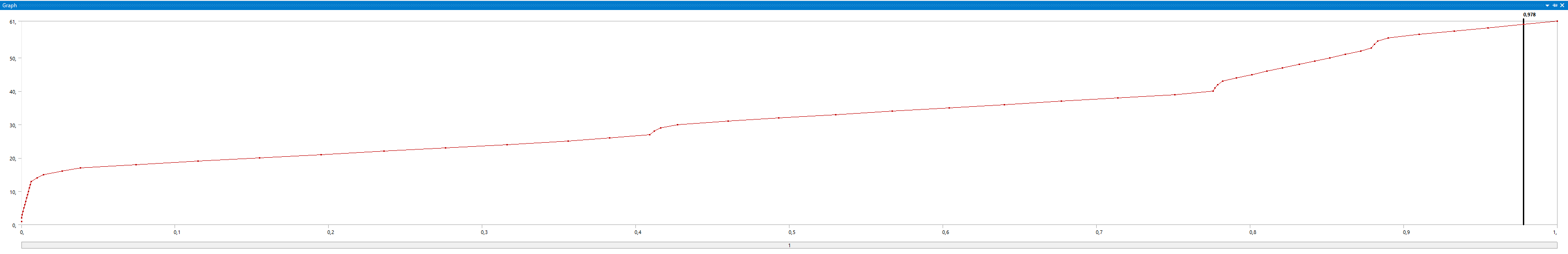
Unfortuntely, I cannot review Newton Raphson Residuals since I am conducting calculations on a cluster and can only download solution files which I then input into Workbench Mechanical Application. (Or is there a way to do so?) But I can view the solution at the last time step before non-convergence occured. I observed that the problem failed at similar step times which correspond to a max. temperature of around 300°C (no matter the mesh size or minimum time step size). Max. equivalent stresses are 8,07E8 Pa. Looking at material data, one can say that yield stress is surpassed and plastic deformation occurs. I therefore have additional material non-linearities. I suspect that this is causing my convergence problem.

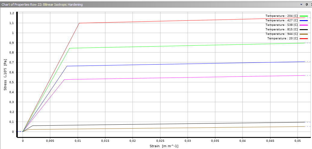
Does anyone know if the stress-strain curve actually continues where the dotted line is shown and data are given? I suspect that it does since bilinear isotropic hardening is defined by tangent modulus.

enter image description here

Material Properties

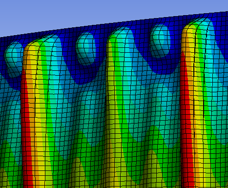
The only error message I obtained at some point (only in one try-out) was that there is exsessive thickness change. No other error messages (of distored elements or similar) show.

Does someone have an idea how I could obtain convergence in this model or what else I could try to analyse the issue? I would be very thankful!

hansophyx
  • 31
  • 1
  • 4

3 Answers3

2

Your model contains a lot of nonlinearities, therefore achieving convergence is not easy. I would try gradually adding each nonlinearity to narrow down where the solver is struggling:

  • turn off large deflections
  • use a linear material behaviour / use a subset of the described material model
  • activate each nonlinearity step by step
  • when that does not help look at a subregion of your geometry and gradually increase it
  • replace the fixed support with a boundary that does not overconstrain the model
  • sometimes the use of MPC contacts can lead to problems. You can try replacing with another contact formulation

Sorry I cannot be more specific but for that I would have to see your model.

meshWorker
  • 75
  • 6
1

First of all, you didn't even mention distinctly that what does the first image that you have inserted here illustrate and represent. What is X axis and what is Y axis. There are numerous graphs present in ANSYS and you are responsible of clearly stating which one have you inserted here in this thread.

Secondly, I don't know if you know this or not, but if you interept the solution (even when its running on cluster), you should be able to obtain the NR residuals for the last 3 (I usually use 3 but you can enter even more) iterations. The solution will automatically stop after completing the current iteration. This way, you can atleast have a practical idea and visualization of which region within your model needs to be closely looked at. Moreover, if you right click the 'Solution Information' while the analysis is running on cluster and then click 'Retrieve', you should be atleast able to import and visualize the running convergence graphs, and then decide if the solution will actually converge or not in the future, and when to Interept/Stop it.

Thirdly, as soon as you increase the number of non-linearities within your model, it becomes more susceptible to encountering convergence problems. Thats why I always try to simplify my model first as much as I can, and get rid of unnecessary non-linearities (which can be converted to linearities essentially for simplification). So naturally, if you input a material non-linearity, there are higher chances that you will face convergence problems. Lower tangent modulus (in the strain hardening region that you have inputted as a bilinear plastic model) actually renders the elements to have increased vulnerablity to element distortion during solution. There is no problem with how you have entered the bilinear palstic model; its absolutely true. Someone might wonder what happens if the strains exceed the Ultimate Strain? Well then there is some bad news. You might observe the dotted lines after the Ultimate Strain, well that line is straight which indicates that after this point the strains keep on increasing while the stresses are constant. This will be exceptionally painful and frustrating to experience because element distortions are the most prominent then. So when you feel like the analysis won't converge by observing their convergence graphs first or when you face a hard error which stops the solution automatically, check and examine the strains and stresses within the patches of your model which you believe are causing the trouble (ofcourse, through the help of NR residuals). Check if the strains and stresses correspond to the bilinear plastic model that you have inputted. If not, then luck is not in your favor. Try switching to linear material model, or try using a different bilinear material model which is relatively more stiff in plastic region (with higher tangent modulus), or try using more MADE-UP data points beyond the Ultimiate Strain and check if this is solving the misery or not.

Additionally, you are using shell elements. Shell elements are much more susceptible to convergence problems that their equivalent solid elements. This is due to the fact that solid elements are much more stiffer than the shell elements because of the mathematics behind them. You will never encounter a excessive thickness change problem in a solid element only model, since this criteria doesn't exist there. Excessive thickness change problem can (I believe) interchangably be used with excessive distortion problem. So I would recommend switching to the equivalent solid elements, or just increase the thickness of the shell elements so that they become increasingly stiff and therefore less prone to excessive thickness change.

Last advice I would be giving you is to manually decrease the time period for each step to an extremely low value, near that time when the solution encounters convergence problem. You might be wondering well you already are using very small timesteps, well guess what? Those timesteps still might not be tiny enough to fetch solution convergence for your model.

Rameez Ul Haq
  • 1,335
  • 8
  • 25
1

You should be able to see Newton-Rapson residuals and element violations. Just turn them on in the 'solution information' field: enter image description here

Choose a value bigger than zero, like 4.

You should also be able to get information from the cluster while it is solving, that is normally done with the 'retrieve' button: enter image description here Note that it only appears when you select 'solution information' in the tree.

Try this in analysis settings: enter image description here

  • Turn on 'auto time stepping'
  • increase the number of steps. Start at 10 and go up to 50 or 100 if needed.
  • Turn on convergence for everything (Force, moment, displacement and rotation).
  • Turn on 'line search'.

The MPC constraints should not be an issue, but you can try different formulations, especially it connections are touching your cyclic boundary.

Orbit
  • 156
  • 5