4

I'm making a dust extractor for a desktop CNC milling machine. My design process was very crude: I looked at some DIY dust-separating cyclones, and it seemed like they just work without any advanced calculations, so I visually copied some of those designs at a smaller scale, sat a large PC cooling fan over the top, and put the whole thing in a coffee can:

Fan in a Can version 2 Fan in a Can v2 cutaway

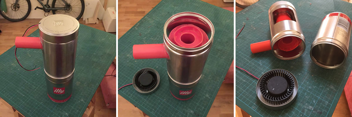
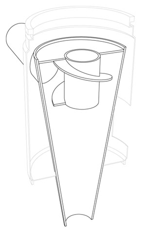
My reasoning was that (1) the 18W fan blows out a lot of air, (2) the only place for that air to come from is through the hole at the top of the cone, and (3) the only way air can get into the sealed cone / dust receptacle (the bottom can) is through the tube at the side. So, it would have to suck a reasonable amount of air through that red pipe.

It does work to some extent (video), but not as well as I hoped. You can see that it barely picks up sawdust through a 1-inch hose, and ideally I'd like it to draw in dust at a range of 20-50mm or so-- I can't position the inlet any closer than that to the point where the dust is created. Plus, I'd like to fit a dust filter over the exhaust hole, which will reduce the air flow even more.

My question is basically "how can I make it suck harder?". But more specifically, how do I start to analyse what's happening, and what determines the amount of air pulled in?

Most Google references are either way over my head, or talk very specifically about pumps in volute casings; obviously I removed the volute casing from my fan in order to fit it in the enclosure. If I understand correctly, the point of the volute is to make the fast narrow stream exiting the fan into a slower, wider stream at higher pressure (why?), and I guess that something similar happens in my can:

Stages of air flow

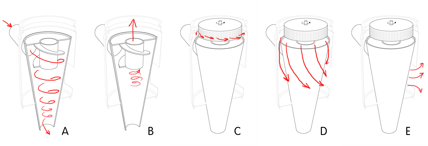
A) incoming air spirals down; dust is thrown out and drops through bottom of cone
B) clean air spirals up through fan inlet
C) fast air exits fan circumference
D) ...and expands into volume below, losing speed and increasing pressure
E) higher-pressure air blown out into atmosphere

Stage C/D is the part I'm most uncertain about. The rest of the design comes from recipes, but I've changed the way air exits the fan and would like to understand how this might affect things.

Edit 4 Feb 2016:

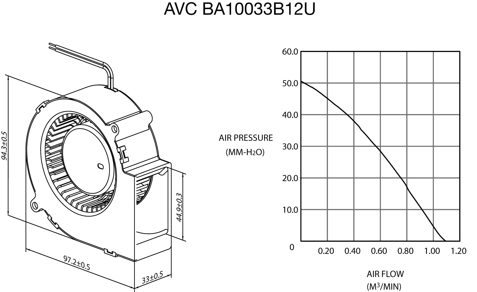
Per @ericnutsch's suggestion, I made rough measurements of the air flowing into stages A and C, and got a figure of about 0.009 m3min-1 at both points. I also found the manufacturer's data for the fan, which suggests I should be able to do better-- the stated max is 1.09 m3min-1. For comparison, my crappy handheld vacuum scores around 0.024 m3min-1. I've ordered a pressure sensor to investigate further...

AVC BA10033B12U fan spec

bobtato
  • 161
  • 1
  • 6

3 Answers3

1

If your cyclone design is correctly separating particles without a major pressure drop; it is working satisfactory and its influence on the flow rate is minimal. If you increase the capacity of your fan and separation starts failing, you may have to modify your design or scale it up.

If you do not have a high enough flow rate, you need to get a larger fan. In addition to this you need to make sure you land at a good location on that fans "fan curve". A fan curve is the relationship between pressure and flowrate. Many fans are rated in maximum pressure (suction is different, but related if you cant get that data) and maximum flow rate. Maximum flow rate occurs at zero pressure drop and maximum pressure occurs at zero flow rate. So in your design you will need to do some testing to make sure the fan you select lands somewhere nicely in the middle.

Some fans that may work well for the application:
Dayton Blowers
Motorized Impellers

ericnutsch
  • 8,305
  • 1
  • 16
  • 32
1

TL, DR You need a stronger and different fan. Try a vac.

What you need to understand about fans
Fans are characterised by their power and their flow-pressure curve. Power is pressure times volume flow. Actualy, that's wrong but it's still useful. You fan delivers a certain and has to overcome a pressure difference. Less pressure - more flow and vice versa. Every system has a pressure drop that rises with flow. The flow will be determined by where the curve of the fan and the system curve meet. Learn more here.

Your system curve (that you don't know) and fan curve meet at 0,009m³/min and 50mm H2O pressure. Take the diagram, draw a straight line through this point and the origin. Pretty steep. The actual sytem curve is somewhere to the left of this line. This tells us that you need a fan that delives a stronger pressure.

What you need to do is IMO attach a vac. cleaner to suction side of your cyclone and try this at different settings.

What you need to understand about cyclones
There's a relationship between how effective a cyclone is and the pressure drop, with more pressure drop meaning more effective separation. Of course cyclones can be designed more or less efficient for a certain duty but with a given cyclone this relationship holds. Pressure drop of the cyclone depends on flow:
More flow -> more speed in cyclone -> stronger centrifugal force to overcome friction (also more pressure drop)

mart
  • 4,811
  • 2
  • 19
  • 32
0

I can think of two ways you might increase airflow in this case - reduce the resistance to airflow or increase the speed of your fan.

For the first case, I'd look at the resistance in the ducts of your system. The 1" exit pipe seems small; most commercial blowers are about 4" in diameter. It should be noted that the resistance to flow in a pipe is proportional to $\frac{1}{D^4}$ of the pipe (airway resistance), so the performance does not scale directly. Small reductions in diameter can have big effects on the flow resistance, AKA back pressure or pressure drop.

You could also speed up your fan. However, there are certain combinations of flow and resistance where a particular fan likes to operate. If you change the speed, you could be improving or reducing the fan efficiency.

Fred
  • 9,782
  • 13
  • 36
  • 48
geekly
  • 206
  • 1
  • 5