This also has a historic reason:
Early microcontrollers' GPIO outputs were designed as open-collector pins with pull-up resistor because the technology used back then (NMOS) did not allow a different design.
This means that inside the microcontroller there was:
- A "large" resistor (typically much larger than 1k) between the GPIO pin to the positive supply voltage
- A transistor between the GPIO pin and the ground
(See the picture below)
If you wanted to use the GPIO pin as output, you had two possibilities as shown in this picture:
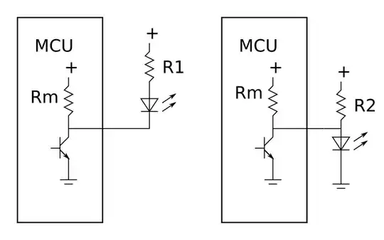
(Note that the resistance of Rm is too large to use it in series to the LED. so R2 had to be in parallel of Rm.)
- The first method is the way it is done in your Raspberry Pi circuit.
Using the resistor R1 you can exactly control the current through the LED.
- The second method would be to shortcut the LED using the transistor inside the microcontroller (right side of the picture).
The value of the resistor Rm had a very broad distribution (e.g. "may be between 2k and 10k") so you had no exact control over the current through the LED.
And when the LED was off, the current consumption of the entire circuit was even higher compared to the circuit with a LED that was on!
So for these reasons you would have preferred the method on the left side in any case.
If you use a microcontroller that has two transistors at each GPIO pin (so-called "push-pull"), you can of course also connect the LED between the GPIO pin and ground.
However, many people still prefer the "old" way of doing it - especially because microcontrollers using only one transistor at each GPIO pin are still produced!

