12

Is there some sort of equivalent standardized schematical (topological) diagram -such as Piping and Instrumentation Diagram, Electrical Schematics, Process Flow Diagrams, etc.- for the realm of mechanical engineering? I just need to draw the overall architecture that would describe the main components of the system and how they are connected, without going into too much detail. I have seen some diagrams but they seem to be ad hoc, as they have no fixed resemblance to each other.

enter image description here

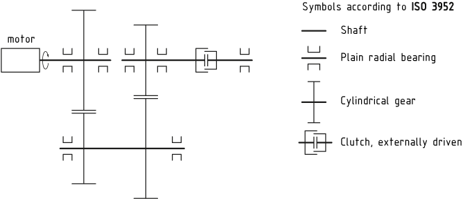
Image 1: I'm looking for something in this complexity.

Maybe there is more than one way to do this but it would be nice to be more universally understood. Looked into OMG SysML but that didt at first glance seem to have what i was looking for.

Brethlosze
  • 238
  • 1
  • 6
joojaa
  • 3,691
  • 1
  • 17
  • 31

3 Answers3

4

The diagram most closely related to the original question seems to be a kinematic diagram. Kinematic diagrams are standardized in ISO 3952, although it seems that most often people are just copying what they have seen without reading the standard (which is quite old, but then this is common anyway).

The standard is in 4 parts and covers symbols, and alternate pictograms for such things as:

  • Simple kinematic pairs such as used in bar linkages (part 1),
  • gears and cams (part 2),
  • geneva drives, ratchets, clutches and couplings (part 3),
  • belt/chain drives, lead screws, flywheels, bearings (part 4).

If we re-draw the image in the original question:

enter image description here

Image 1: Kinematic diagram, uses the same thin thick line style as normal engineering drawings.

ISO 3952 standard does not have a motor symbol. That is because they are concerned with motions not dynamics. Either way it is a human readable format so you can always add your own clarifications.

joojaa
  • 3,691
  • 1
  • 17
  • 31
1

Even though I can't find any standardized literature, the theory behind of what you seem to be looking for is the so called systems modelling. Peter E. Wellstead published (can be accessed here: www.control-systems-principles.co.uk) his efforts in "formulating a simple unified approach to system modelling" that could set a framework for handling mechanical systems using the exchange of energy of it's elements as the unifying key point. The result of this approach is a simple and manageable method to model lumped systems.This method uses differential equations and a set of graphical representation alternatives, namely network methods (topological network used traditionally in electrical circuits) or bond graph methods.

Here is an example of the topological representation as requested in your question:

Example of a Mechanical System represented by a Network

In his book you'll find other examples of more complex mechanical systems:

  • The ball and the beam problem
  • An automotive test bed

Good luck!

Edit: I don't yet have permission to publish links but the mentioned book can be found at www"dot"control-systems-principles"dot"co"dot"uk .

pedrez
  • 193
  • 1
  • 2
  • 11
0

There is, it looks like this here: enter image description here

I don't know it this is standardized, but it is used quite often like this. In university the questions in exam looked sometimes like this.

joojaa
  • 3,691
  • 1
  • 17
  • 31
MaestroGlanz
  • 132
  • 6