To determine the properties of a composite laminate, the properties of each component and their relative volume fractions must be known.
The properties of glass fiber laminate may be determined using the rule of mixtures. Consider a cross-section of the fiberglass laminate as shown below.
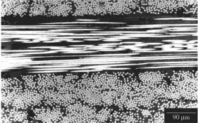
White regions are the fiberglass, black regions are the epoxy matrix. The white dots are transversely-sectioned fibers, and the white highly-eccentric ellipses are longitudinally-sectioned fibers. If we consider only the bottom portion of the image, so that all the fibers are aligned into and out of the image, then it appears that about 50% of the volume is occupied by fibers and 50% by matrix, which is a reasonable mix.
From the rule of mixtures:
$$
E_c = E_f V_f + E_m V_m
$$
where the subscript $c$ denotes composite bulk, $f$ denotes fiber, and $m$ denotes matrix, and $E$ is tensile modulus and $V$ is volume fraction. Then because the tensile modulus of the fibers are $E_f=70\ \textrm{GPa}$ and of the matrix is $E_m=2\ \textrm{GPa}$ (give or take a little), the composite modulus $E_c$ is
$$
E_c = (70\ \textrm{GPa})(0.5)+(2\ \textrm{GPa})(0.5) \\
E_c = 35\ \textrm{GPa} + 1\ \textrm{GPa} \\
E_c = 36\ \textrm{GPa}
$$
For strength, the situation is a bit more challenging, and depends on elastic compatibility. Since we know the stiffness of the composite, $\sigma_{f,UTS}=2\ \textrm{GPa}$ for E-glass fibers gives the strain at failure by the relationship $\sigma_{f,UTS}/E_f=\varepsilon_f=0.029$. Similarly for the matrix assuming $\sigma_{m,UTS}=0.085\ \textrm{GPa}$ gives $\varepsilon_m=0.043$. Since the strain at failure is lower for the fibers, they fail first, by compatibility. The strength of the composite is then the product of strain at failure and composite modulus, or about $1\ \textrm{GPa}$. This result also assumes the interface doesn't fail before either of the components, hence the need for cleanliness and full wetting of the fibers.
Deflection may be calculated by assuming the shelf is a beam, and using the worst-case, i.e. 100kg centered load and simply supported at the ends, and not supported at the wall. The equation for the deflection is
$$
\delta_{center} = \frac{FL^3}{48\sum EI} \\
= \frac{\left(980\ \textrm{N}\right)\left(8\ \textrm{m}^3\right)}{48\left[\left(36\times 10^9\ \textrm{N}\cdot\textrm{m}^{-2}\right)\left(8.4\times 10^{-9}\ \textrm{m}^4\right)+\left(2.5\times 10^9\ \textrm{N}\cdot\textrm{m}^{-2}\right)\left(5.8\times 10^{-6}\ \textrm{m}^4\right)\right]} \\
= \frac{7840\ \textrm{N}\cdot\textrm{m}^3}{7.1\times 10^{5}\ \textrm{N}\cdot\textrm{m}^{2}} \\
= 0.011\ \textrm{m} \\
\approx 1\ \textrm{cm}
$$
Which is your desired value, but with no safety factor. I've assumed for simplicity that the neutral axis is at the midplane, which is inaccurate. The actual location is the elasticity-weighted centroid of the laminate area. The neutral axis should be shifted away from the laminate to compensate for its increased stiffness. The effect on the area moment of inertia of the laminate should be to increase it and with its greater stiffness should result in a smaller deflection.
Image comes from aerospaceengineeringblog.com