Disclaimer: Although I have studied FFT, I have not applied FFT to a practical application. Therefore I would differ a direct response to someone else. Regardless I would really like to see the end result too.
But I can offer you following two application examples and source code to access data from three axis ADXL345 accelerometer to help you with your endeavors. Examples were developed on ARM Cortex A8 and ARM Cortex M4 processors. The first one uses a Beaglebone Black / Embedded Linux platform and the second is a bare metal design. All X, Y, and Z data points are captured. These are used to calculate Roll and Pitch.
Three axis ADXL345 accelerometer implementation using a Embedded Linux platform
Three axis ADXL345 accelerometer implementation using a Embedded Linux platform
Both the designs use I2C bus to capture the data. So digitally sampled data is available. Therefore code has to modified to apply FFT. With little effort you should be able determine frequencies, harmonic's etc.
Your are welcome to fork the source code and use them as you wish.
Also below are few interesting graph on that might be of help.
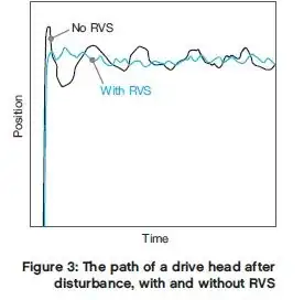
Rotational Vibration Safeguard (RVS)
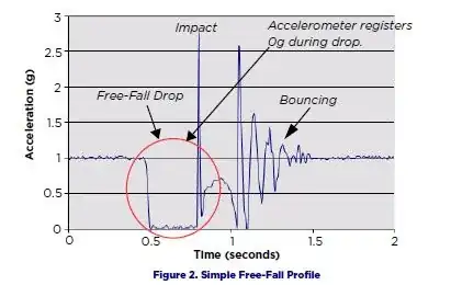
Simple Free fall profile for a HDD
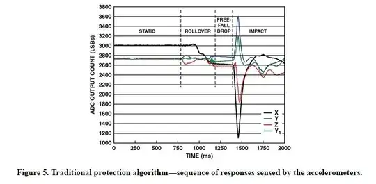
A Traditional Protection Algorithm
Traditionally, the HDD protection algorithm has been based on
free-fall modeling, as explained below, in which the outputs of the
sensors contained in the accelerometers can be easily captured by a
digital oscilloscope or other data sampling system.
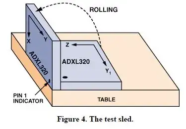
A “test sled” can be assembled using two ADXL320 dual-axis
accelerometers. The axes of the accelerometers are aligned with the X,
Y, and Z axes, as depicted in figure below (Figure 4), thereby providing
values of acceleration along the X, Y, and Z coordinates. (The Y1 output is
redundant and is not used.) The outputs of the coordinate axes are
sampled by a 12-bit ADC contained in an ADuC832 precision analog
microcontroller, which integrates the sampled data and feeds it to an
internal 8052-compatible core processor. The sampled data is then
transferred to the computer—via an RS-232 interface—for analysis.
The figure below (Figure 5) shows the sequence of responses sensed by the two > sensors. Values X and Y are supplied by one accelerometer, the values Z and Y1
are supplied by the other accelerometer. Note also that the plot is
divided into four consecutive intervals labeled: “static,” “rollover,”
“free-fall drop,” and “impact.” The sampling interval, shown along the
X axis, is determined by the ADC, which is clocked at 200 Hz for each
variable, or one sample of each variable every 5 milliseconds. The
Y-axis scale represents the values delivered by the 12-bit ADC in the
ADuC832 smart-transducer front end, plotted for all four axes.
References:


