4

Here's a column top which holds a driveway overbridge.

enter image description here

The column is a reinforced concrete cylinder with an inverse truncated cone on top - so it expands sideways at its top. The column top holds some narrow thunk and that thunk holds the driveway floor.

Note that the thunk cross section square is much, much smaller than the column top cross section square, so it looks like the column top is overbuilt and the top is too wide for no reason - the thunk could rest on the column top even if the column had no expansion.

Why would this design be used instead of a cylinder?

sharptooth
  • 2,129
  • 19
  • 28

3 Answers3

6

The column top holds some narrow thunk and that thunk holds the driveway floor.

I think we have some nomenclature that needs to be cleared up here.

What I believe you're calling a "thunk" is actually a bearing plate. This is a little steel platform that transfers the load from the bridge to the column.

bearing plate
(source)

The expanded portion at the top of the column is called a capital.

capital
(source)

Note that the thunk cross section square is much, much smaller than the column top cross section square, so it looks like the column top is overbuilt and the top is too wide for no reason - the thunk could rest on the column top even if the column had no expansion.

You have two different materials here that have different strengths. Steel has usually 4-10 times the compressive strength that concrete does. Thus, a much smaller cross-section (in terms of area) of steel can carry a load than a concrete cross-section can.

As to why the column capital is much wider than the bearing plate, this is likely because the bearing area is being distributed into the column cross-section, similar to the image below (excerpt from the PCI Design Handbook, 7th Edition).

bearing dist

Why would this design be used instead of a cylinder?

The inverted tapered cone for the capital could either be a design choice (to increase the bearing strength) or an aesthetic choice. We have no way of really knowing without looking at the calculations.


EDIT:

This might be a wild shot, but they could have flared the top of the column to make placing concrete easier. Kind of like pouring something into a funnel. However, I kind of doubt it.

grfrazee
  • 3,597
  • 1
  • 18
  • 33
2

I find such a column hard to justify.

As mentioned by @grfrazee and @ChrisJohns, what you are calling a "thunk" is usually called a bearing plate, and these are responsible for transmitting the force from the superstructure (beams) to the mesostructure (columns).

As mentioned by @ChrisJohns, these bearing plates may well be bolted, in which case a minimal distance to the edge of the column is necessary. That being said, these distances are usually quite small, and at a glance it seems to me that the smaller column diameter would be sufficient to satisfy that distance.

@grfrazee defines the flaring as a capital, but I'm not sure that's what we're seeing here. Capitals are mostly used when a column supports a slab directly (as opposed to supporting a beam which supports a slab). Their purpose is to increase the contact area and therefore decrease the punching force on the slab. Given that these columns are not supporting slabs (and even if they were, the bearing plate forces a concentration of punching force regardless), I don't think the flaring of the column is meant to be a capital.

@grfrazee's image (repeated below) also raises another problem with this flared column head. By increasing the size of the column, they have increased the size of area $A_2$ in the figure below. This increases the bearing strength at the head, but if this compression were the ruling factor, you'd have the same problem away from the "capital", once the section is reduced.

a

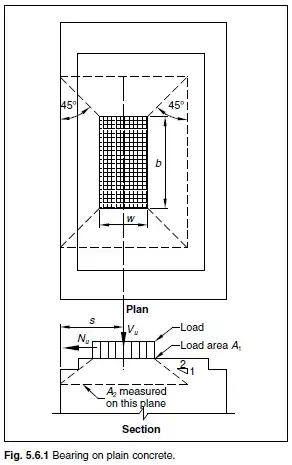
The ratio $\dfrac{A_1}{A_2}$ (as opposed to $\dfrac{A_2}{A_1}$ when calculating bearing strength) is used when calculating the splitting forces at the head of the column, and the smaller this ratio (or, the larger $A_2$ is in proportion to $A_1$), the greater the splitting forces.

So honestly, I can't really see a valid motivation behind using such a column.

grfrazee
  • 3,597
  • 1
  • 18
  • 33
Wasabi
  • 13,167
  • 8
  • 39
  • 62
1

Columns like this are often connected to the horizontal elements of the structure they support by bearings which are designed to support the vertical load from the weight of the structure but not transfer horizontal loads to the columns. This ensures that the columns are loaded only in compression and allows movement of the structure they support (in this case the steelwork of the bridge deck) without putting unwanted loads on the columns.

The design of the bearing can vary and depends on the design requirements and may be eg rocker, pinned, mechanical thrust bearings or elastomer based. Clearly for a long span bridge the range of movement can be quite significant, especially is allowances are made for resistance to impacts or earthquakes.

There are a few reasons why the top of the column might be flared. If the bearing is bolted on then bolted connections in concrete require a minimum distance for the edge to spread their load effectively and to mitigate corrosion. As mentioned in other answers the exact solution will come down to detailed design choices and analysis but the short answer is that it is to accommodate the bearing

Chris Johns
  • 15,326
  • 3
  • 24
  • 42