6

So I'm trying to understand the pin layout of an Ethernet port, specifically for 8P8C which to my understanding is the most common. Of the eight pins, only four are apparently used for communication, as depicted below where pin 1 and 2 are TD+ and TD-, and pin 3 and 6 are RD+ and RD-. (Where TD = transmit, RD = receive)

enter image description here

I understand that they're lined up this way due to the cable pairs in the Ethernet cable

enter image description here

However what I don't understand is why there's a seperate + and - transmission and receiver line, and what they do. Are they each carrying their own signal? Or is one a reference voltage?

For context my goal is to create a full-duplex fiber line and convert it back into an Ethernet cable so I can plug it into my computer, and I want to better understand the difference between the + and - line so I can convert it into an 8P8C connector.

Thanks for your help!

Zac67
  • 90,111
  • 4
  • 75
  • 141
thansen0
  • 163
  • 1
  • 1
  • 5

8 Answers8

17

Twisted pair uses differential signaling - in a pair, one wire is always the negative/complimentary signal of the other. In the simplest example, Transmit+ > Transmit- (higher voltage level) means 1 and Transmit+ < Transmit- (lower voltage level) means 0. Put in another way, each wire is a reference for the other. There is no reference to ground.

For 10BASE-T and 100BASE-TX there's a dedicated pair each for transmitting data and receiving data.

With fiber there's no need to compensate EM noise or to remove direct current, so you can just put a data signal on the core. You can buy cheap media converters for connecting e.g. 100BASE-TX and 100BASE-FX, or 1000BASE-T and 1000BASE-LX. Building that yourself is a major project - in addition to the transmission medium, the line codes can be quite different for fiber and copper:

  • 10BASE-T to 10BASE-FL could be directly adapted, Manchester throughout
  • 100BASE-TX to 100BASE-FX would require PMD de/encoding (-TX uses MLT3) and scrambling/unscrambling, but the PCS is the same 4b/5b
  • 1000BASE-T to 1000BASE-LX requires complete PCS transcoding (-T uses four-dimensional PAM5 & scrambling; -X uses straight 8b/10b)

[Edit] As Criggie has pointed out, using a modular transceiver (SFP) with a decent switch is preferable to an external media converter.

Zac67
  • 90,111
  • 4
  • 75
  • 141
4

Great question. Zac67 did a great job of answering it, but I'd like to give my own take on it.

Your question revolves around two other, but related questions:

  1. Why does UTP use a pair of wires?
  2. Why does UTP twist the wires around each other?

Both questions have to do with Electromagnetic Interference (EMI). The first mainly reduces outbound EMI, the second reduces inbound EMI.

Why does UTP use a pair of Wires?

Voltage applied to a wire emits outbound EMI. If there is only one cable in use, then that isn't much of a problem. But often cables are run alongside many other cables, and the idea of one cable's outbound EMI affecting the transmissions of other wires next to it is undesirable.

The solution devised is to transmit two signals inverse from each other.

For example, presume we need to send a voltage of +5v from one end of a cable to the other. Presume transferring +5v leaks +0.5v to neighboring cables. To offset this, use another wire to transfer the exact opposite: -5v, which will have the effect of also leaking -0.5v to neighboring cables. The combined effect of leaking +0.5v and -0.5v ends up being outbound emission of 0v.

(It isn't a perfect net 0 emission, but you can see the concept).

This is referred to in the electrical engineering world as a Balanced Pair, and is represented in twisted-pair wiring with the TX+ and TX- wire.

This allows you to use wiring schemes that don’t require heavy investments in shielding, and is a part of the reason for the prolific use of Unshielded Twisted Pair (UTP) cabling instead of Shielded Twisted Pair (STP)

So far we’ve only answered why we use a pair of wires, we will look into why they are twisted next.

Why does UTP twist the wires around each other?

Despite the strategy above of using a Balanced Pair, there is no avoiding the fact that any electrical wire will be exposed to some amount of inbound EMI. To offset this, another strategy was devised to reduce the absorbed EMI on a Balanced Pair.

The strategy revolves around the fact that the EMI interference will be greater the closer a wire is to the source. If two wires, who are sending the opposite voltage on a wire, "take turns" being closest to the source, they will both be exposed to the same amount of inbound EMI. Allowing the receiving end to extract the intended signal from the EMI.

Here is how that works:

Practical Networking - Ethernet Wiring

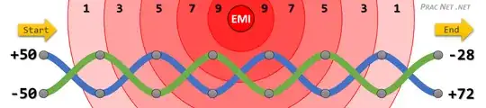
The blue wire starts with +50v, and the green wire starts with the exact inverse, -50v. The source of the EMI is the red circle, and each wave that surrounds the EMI source impacts the wires progressively less and less. If you only add the EMI at each grey dot (the top and bottom of each twist), both wires end up receiving +22v of interference.

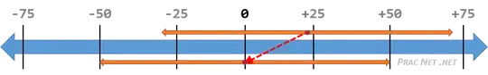
Even though the final voltage received on the right side of the wire is different, notice that the difference in voltage is consistent throughout the twisted pair of wires: it is always 100v apart. The EMI affected both wires identically. You could easily calculate the difference of the final values (100v), and display it on a number line to determine the starting voltages were +50v and -50v:

enter image description here

It should be said that the numbers used above were greatly simplified in order to communicate the concept. Typical EMI emission only affects signaling in the range of micro-volts (µV) — which is 1,000,000th of a Volt (V). But the concepts still remain true: because the original and inverse signals are being sent, the net outbound emission is canceled out, and because of the twists, both wires are equally exposed to the same amount of interference.


With all that said, we can speak directly to your questions:

However what I don't understand is why there's a seperate + and - transmission and receiver line, and what they do.

Are they each carrying their own signal?

Yes, but they are inverse of each other.

Or is one a reference voltage?

Yes, they are a mutual reference for each other.


The images and content above come from this section of an article on Ethernet Wiring on my blog. If you want to learn more about the subject, feel free to take a look.

Eddie
  • 15,286
  • 6
  • 46
  • 84
3

Are they each carrying their own signal? Or is one a reference voltage?

I don't know how much you know about electronics, so I will explain the background first:

In principle, you need two wires for an electric current to flow. For many types of connections there is one separate wire for each signal and one common wire for all signals. This common wire is typically called "ground" or "earth".

An example: The Centronics printer interface has up to 17 signals while at least 8 of them are used. If you want to "send" some signals to the printer, electrons flow through the 17 wires that represent the 17 signals. The electrons flow back through the "ground" wire.

Many other types of low-frequency computer cables (such as VGA, analogue audio, RS-232, VGA, PS/2 or the power supply) use the same principle: One wire for each signal plus one "ground" wire which is common for all signals.

For high-frequency signals such as Ethernet, DVI, SATA and USB, signals would disturb one another massively when not considering certain effects. One of many things that will cause disturbance is using one common wire for more than one signal.

This means that each signal requires its own two wires.

What do the positive and negative (+/-) transmit and receive pins mean on Ethernet cables?

In such cases "plus" and "minus" are typically only used to distinguish the cables if it is not allowed to exchange them (you are not allowed to exchange "Tx+" and "Tx-").

Martin Rosenau
  • 2,366
  • 8
  • 10
3

As Zac67 says, the two wires form a differential pair; the difference in voltage between the two wires is what's significant at the receiving end.

The reason this is done is that it improves resistance to noise. The two wires are twisted together in close proximity, so any electromagnetic interference that hits one wire hits the other wire with almost exactly the same change in voltage, so the differential voltage stays almost identical.

2

Why 2 wires? to protect from interference!

Think of two sea-saws connected together by 2 tight bits of string to each ends of the sea-saws. When you move sea-saw No.1, one string pulls and the other releases as a result sea-saw No.2 mirrors the movement if interference comes along it pushes or pulls on both strings equally especially as they are twisted together. As a result the sea saw doesnt move

chris

chris
  • 21
  • 2
0

Nothing meaningful. They're just markers. They could've been named whatever, but the plus-minus pair has the advantage of making most people extra careful to not swap them. Which is the whole and only point of marking them apart.

Building your own "stupid" transceiver is rather difficult. If you limit yourself to 10 or 100, you'd need 2 unidirectional fibers. 1000 is quite complex, as you'd need 4 lines that can change direction whenever they feel like. If your goal is to learn, the go for 10. If you want to have something reliable, fast or save money, buy something off the shelf. Used server stuff is cheap, if that's your goal, otherwise new stuff is still affordable.

Agent_L
  • 151
  • 3
0

Zac67's answer is good for why there are two wires per signal.

What they do is complicated, besides transmit/receive of binary data by analog signal, Ethernet mixes in a media sharing protocol which is a huge part of why it has been so successful. Media sharing is how multiple endpoints (users) share the same set physical media for networking. Back in the day before internet protocol, computer networks were created by connecting everyone with the same two wires to communicate. And many protocols were invented to handle the problem of media sharing. The carrier sense multiple access with collision detection (CSMA/CD) that made Ethernet is still the preferred protocol for local area networks. But switches have done away with essentially all of the collision problems.

Now if you're not convinced you should just use something off-the-shelf, then you still want to project up your fiber-optic link.

Two ways to go as I see, use the fiber to transmit the analog UTP signal or to transmit the digital data after decoding it from the UTP signal. You could convert the analog signal from the UTP to transmit over fiber via whatever scheme you're interested and then just pump that signal back into UTP on the other side. This would let you learn about transmission via analog models.

You could alternatively decode the binary from the ethernet and then encode it onto the fiber line by some digital-to-analog signal generation scheme. This will let you use use models to handle both the binary encoding (and decoding) as well as the analog transmission.

You ought to spend some of your research time looking at the IEEE 802.3 standard. It's kinda expensive, but I got it free through my university library. I saw something in there about synchronicity of the two signals, so you might need to make sure you bake that into your project.

Also Wikipedia talks about how the binary is encoded for UTP transmission.

With 100BASE-TX hardware, the raw bits, presented 4 bits wide clocked at 25 MHz at the MII, go through 4B5B binary encoding to generate a series of 0 and 1 symbols clocked at a 125 MHz symbol rate. The 4B5B encoding provides DC equalization and spectrum shaping. Just as in the 100BASE-FX case, the bits are then transferred to the physical medium attachment layer using NRZI encoding. ...

It sounds like a neat project to me.

Drist
  • 1
  • 1
-1

It's doesn't take a attention , it's just the simple thing behind why TX+ and TX - separately...? If I'm not wrong then A 10BASE-T cabel carry Unidirectional voltage only means transmitter sends two differential voltages, +2.5 V or −2.5 V. So that for there's one link for the Positive voltage (TX+) and For Negative Voltage (TX-) . Same like Transmitted single there are 2 different Voltage links for Receiver side ..