0

I have the following exercise:

Design a circuit that takes a 2 bit binary and makes it x^3 (x cubed), using a decoder 
of your choice.

I thought to do it with a 3 to 8 decoder, because I have 2 bits of input, and 4 bits of output, since the largest output is 11011 (which is 27 in decimal).

I have managed to get to a truth table. Input = \$x_0x_1x_2\$. Output= \$a,b,c,d,e\$.

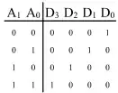
\begin{array}{|c|c|c|c|c|c|c|c|} \hline x_0 & x_1 & x_2 & a & b & c & d & e \\ \hline 0 & 0 &0 &0 &0 &0 &0 &0\\ \hline 0 &0 &1 &0 &0 &0 &0 &1\\ \hline 0& 1 &0 &0 & 1 &0 &0 &0\\ \hline 0 &1 &1 &1 &1 &0 &1 &1\\ \hline \end{array}

However, I am not quite sure what should I do now. I have to get to a function to represent it in gates? How can I make a karnaugh map from that table?

I am aware that I would have to add three more outputs to the 3 to 8 decoder, but they will be just "don't cares".

Your help is appriciated.

KillaKem
  • 1,750
  • 2
  • 13
  • 27
Alan
  • 125
  • 8
  • If you were not using the decoder, I would say to draw 5 small Karnaugh maps, one for each output, using your 2 bits of input. Since you are using a decoder, there is no need for Karnaugh maps. Just follow Brian's advice. – Tut Jun 26 '14 at 11:25

2 Answers2

3

With some thought you can do it with less logic ... a single 2-input gate.

I'll not give the whole game away, but one technique that may help is to treat each output bit individually, and minimise the logic for that output alone.

Start with bit c as it is the simplest.

Then put the individual solutions together.

  • Actually, it looks like he needs no extra gates at all (assuming he uses the required decoder) – Tut Jun 26 '14 at 12:10
  • Right : the trick is to use a decoder to mimic a simple gate... –  Jun 26 '14 at 12:13
  • +1 This took me a moment but I see it. Very clever observation. At least the solution I see requires a single gate as Brian had suggested. I am not sure how this would be done with only a decoder and no external logic? – sherrellbc Jun 26 '14 at 13:20
  • @sherrellbc Perhaps if you drew the truth table for a 2 to 4 decoder, it would be more obvious. (still trying to avoid showing the solution directly) – Tut Jun 26 '14 at 13:24
  • @BrianDrummond I understand why the input is 2 bit long, but I don't understand why the output is 4 bit long? because 3^3 is 27 - a 5 bit outpout. – Alan Jun 26 '14 at 19:46
  • 1
    @BrianDrummond I think I might got it. I got expressions for all the outputs: a=x1x2, b=x1, c=0, d=x1x2, e=x2. Now when I make the circuit I just connect the gates? I'm not exactly sure I should I treat d and a since they're equal. Please correct me if I'm wrong, and I thank you for your help. – Alan Jun 26 '14 at 20:09
  • 1
    I never said anything about 4 bits of output : but in a sense, you DO only have 4 bits of output because a and d are equal. I would simply connect them together. (In a large design there are other considerations - read about "fanout" in TTL logic - but not here.) –  Jun 26 '14 at 20:20
  • @BrianDrummond, thank you. So, I think I might got it right. My question is, what is the decoder's work here? I mean, I could have not used it at all here! – Alan Jun 26 '14 at 20:24
2

To answer the question in general, from this point you would look at each output variable and construct the appropriate logic on that line.

Each of your output variables, in general, will be constructed independent of the others. However, there are often cases where there is similarity (or they are identical) and as such may be formed used into a single logic configuration and taken twice on the output. The following is taken directly from the wiki.

For instance, the truth table for a 2 to 4 decoder looks like this:

http://i.imgur.com/68oe6ce.png

Where the output expressions are derived for each respective output variable with respect to the input states.

http://i.imgur.com/N622HPl.png

And from these expressions you can directly design the decoder:

http://i.imgur.com/cOBxAss.png

sherrellbc
  • 3,451
  • 7
  • 35
  • 63
  • @sherrllbc I understand why the input is 2 bit long, but I don't understand why the output is 4 bit long? because 3^3 is 27 - a 5 bit outpout. – Alan Jun 26 '14 at 19:46
  • Which output? The output of the decoder schematic I presented above? – sherrellbc Jun 26 '14 at 19:48
  • No, the output bits I have shown in the table in the original post. Thank you btw! – Alan Jun 26 '14 at 19:50
  • I think I might got it. I got expressions for all the outputs: a=x1x2, b=x1, c=0, d=x1x2, e=x2. Now when I make the circuit I just connect the gates? I'm not exactly sure I should I treat d and a since they're equal. Please correct me if I'm wrong, and I thank you for your help. @sherrellbc – Alan Jun 26 '14 at 20:10
  • Yes, that is what Brian was talking about above. For the case that a=d just have the output of x1*x2 taken to both bits a and d. No big deal there. – sherrellbc Jun 26 '14 at 20:15
  • @sherrelbc, thank you. So, I think I might got it right. My question is, what is the decoder's work here? I mean, I could have not used it at all here! – Alan Jun 26 '14 at 20:24
  • You got it. You can realize what you are asking for with a simple 2-input AND gate. According to Tut you may somehow realize the circuit with only the decoder but I do not quite see how. Perhaps now that you have solved the original problem he will come back and post his slick implementation. @Tut – sherrellbc Jun 27 '14 at 12:13