2

enter image description here

I was about to apply nodal analysis via inspection (to make it faster) to the above circuit, yet as we can see, it has a dependent source. So listing the equations for node(1 and 2) supernode a:

$$v_1(\frac{1}{2} + \frac{1}{6}) + v_2(\frac{1}{4}) -v_3(\frac{1}{6}) = 0$$

$$v_2(\frac{1}{4}) + v_3(\frac{1}{3} + \frac{1}{6}) - v_1(\frac{1}{6}) = 0$$

$$v_1-v_2 = 10V$$

Yet, it yields incorrect results (I tried solving it yet get wrong results). Are there any restrictions to nodal analysis by inspection when it has supernodes with dependent sources?

PS: correct answer are: \$v_1 = 3.043V\$, \$v_2 = -6.956V\$ and \$v_3= 0.6522V\$

Revision 2: instead of doing it the traditional way (like writing KCL equations), we can solve it via inspection. Are u familiar to it: The Inspection Method for Nodal Analysis and Nodal Analysis? I'm trying to apply solution by inspection here but it doesnt work the way it should be (notice my equation above).

Ricardo
  • 6,164
  • 20
  • 53
  • 89
vvavepacket
  • 2,503
  • 9
  • 41
  • 57
  • Re your revision 2: OK, now I understand what you're trying to do. I believe it is the case that this "inspection" method is valid only for circuits with resistors and independent sources. – Alfred Centauri Jul 29 '12 at 21:35
  • hmm, but i see some examples with dependent sources where the "inspection" works fine.. hmmm – vvavepacket Jul 29 '12 at 21:44
  • Take a look at slide 55 of the 2nd link you provided: "3.6 Nodal and Mesh Analysis by Inspection. a) For circuits with only resistors and independent current sources. b) For planar circuits with only resistors and independent voltage sources." – Alfred Centauri Jul 29 '12 at 21:48
  • I've taken a look at this article and I think I see what's going on. I believe this "inspection" method is essentially nothing other than superposition. Now it is claimed that superposition is invalid for dependent sources but it is, in fact, the case that superposition can be used with dependent sources (you do have to be careful though) so... it may be that this inspection method can also be used with dependent sources. I'm still looking at it. – Alfred Centauri Jul 29 '12 at 22:01
  • My bad, i was wrong, you must make a big supernode. My eqs are wrong. Tnx to alfred – vvavepacket Jul 31 '12 at 11:39
  • I really didn't see an issue here. To me that is clearly a "current controlled voltage source". –  Oct 17 '12 at 06:41
  • Which is a better way to solve this problem, Cramer's rule or elimination technique? And I can't get the answer with Cramer's Rule! –  Mar 10 '15 at 06:27

3 Answers3

3

edit
If the numbers you've added in your PS are indeed correct then the assignment contains an error. "\$ 5 \text{ }i\$" has the dimension of current, if it should have been a voltage it should have said "\$ 5 \Omega \text{ }i\$". My answer assumes what the schematic says, not what may have been intended. I've added the answer for the corrected assignment below.
end of edit

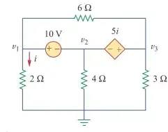
Like I said in my answer to your other question, draw the chosen current directions so that you don't get confused and switch one of the directions halfway the calculation. I'll use the resistor values as current index, so the current though the 3 Ω resistor is \$I_{R3}\$.

enter image description here

I'm not sure what this supernode is, but I presume you want to apply KCL to a region instead of a single node. You'll have to clarify what this region is, because with the current equations there must be a mistake.

Anyway, we don't really need a supernode, you can set up a set of simultaneous equations as follows:

For the node \$v_1\$:

\$ I_{10V} = I_{R2} + I_{R6} \$

For the node \$v_2\$:

\$ I_{10V} + 5 I_{R2} + I_{R4} = 0 \$

For the node \$v_3\$:

\$ 5 I_{R2} + I_{R6} = I_{R3} \$

and

\$ v_1 = 2\Omega \cdot I_{R2} \$

\$ v_2 = 4\Omega \cdot I_{R4} \$

\$ v_3 = 3\Omega \cdot I_{R3} \$

\$ v_1 - v_3 = 6\Omega \cdot I_{R6} \$

We have 7 equations for 8 variables, so we need another independent equation:

\$ v_1 = v_2 + 10 V \$

This set of linear equations is easy to solve with some substitutions, and the result is:

\$ \begin{cases} v_1 = 0.989 V \\ v_2 = -9.01 V \\ v_3 = 5.27 V \\ I_{R2} = 0.495 A \\ I_{R3} = 1.76 A \\ I_{R4} = -2.25 A \\ I_{R6} = -0.714 A \\ I_{10V} = -0.220 A \end{cases} \$


The solution for the corrected assignment:

enter image description here

\$ v_1 = v_2 + 10 V \$

\$ v_3 = v_2 + 5 \Omega \cdot \dfrac{v_1}{2 \Omega} = v_2 + 2.5 v_1 \$

and applying KCL to the ground node:

\$ \dfrac{v_1}{2 \Omega} + \dfrac{v_2}{4 \Omega} + \dfrac{v_3}{3 \Omega} = 0 \$

That gives us a set of 3 simultaneous linear equations in 3 unknowns, which indeed gives us

\$ \begin{cases} v_1 = 3.04348 V \\ v_2 = -6.95652 V \\ v_3 = 0.652174 V \end{cases}\$

stevenvh
  • 145,832
  • 21
  • 457
  • 668
3

Your supernode should enclose both sources. Your KCL equation is then:

\$\dfrac{v_1}{2} + \dfrac{v_2}{4} + \dfrac{v_3}{3} = 0\$

Then, you need three more equations (you have four unknowns):

\$v_1 - v_2 = 10V \$

\$v_3 - v_2 = 5\Omega \cdot i \$

\$i = \dfrac{v_1}{2\Omega} \$

Solve to get:

\$v_1 = 3.043V\$

\$v_2 = -6.956V\$

\$v_3 = 0.6522V\$

\$i = 1.522A\$

Ricardo
  • 6,164
  • 20
  • 53
  • 89
Alfred Centauri
  • 26,630
  • 1
  • 25
  • 63
  • That's what OP also found, but I get another result. With these values the current from the current source is 7.61 A, the current through the 6 $\Omega$ resistor 0.398 A towards v3, that's a total of 8.01 A, but the current through the 3 $\Omega$ resistor is only 0.22 A. – stevenvh Jul 29 '12 at 18:13
  • I think the problem is in the "v3 - v2 = 5 i". The dimensions are wrong here: LHS = volts, RHS = amperes. – stevenvh Jul 29 '12 at 18:15
  • The controlled source has a transresistance of 5 $\Omega$; the voltage across the source is $5 \Omega * i$ – Alfred Centauri Jul 29 '12 at 18:29
  • Ah, but that's not how I understand it. OP says he has a dependent current source. As I understand it the current is 5 times the current through the 2 $\Omega$ resistor. – stevenvh Jul 29 '12 at 18:32
  • 1
    I see that your equations are treating the source as a current source. I'm thinking it's a voltage source as I usually use an arrow rather than + - inside the body for a current source. So, the OP has solutions for both cases now! – Alfred Centauri Jul 29 '12 at 18:34
  • 1
    I'm not treating anything! :-). I'm just applying what the schematic says: that there's a current through that branch 5 times i. That it's a current source follows from the results: the 5 x i flows from a lower to a higher voltage. The symbols are no good: the circle suggests a voltage source, while it's a resistor in both our solutions. – stevenvh Jul 29 '12 at 18:45
  • I think the symbols are fine. See, for example: link. The schematic shows what I recognize to be a CCVS, current controlled voltage source. – Alfred Centauri Jul 29 '12 at 18:50
  • In that case the assignment contains an error. It should say "5 $\Omega$ $i$. What's shown has the dimension of current. – stevenvh Jul 29 '12 at 18:56
1

This should work.

At the supernode consisting of \$v_1\$, \$v_2\$ and \$v_3\$ (the supernode encompasses both the independent and dependent voltage supplies):

$$\frac{v_1}{2}+\frac{v_1-v_3}{6}+\frac{v_2}{4}-\frac{v_1-v_3}{6}+\frac{v_3}{3} = 0$$

Conditional equations:

$$v_1-v_2 = 10V$$

$$v_3-v_2 = 5 \frac{v_1}{2}$$

Variables:

$$[v_1,v_2,v_3]$$

Results:

$$v1 = \frac{70}{23} = 3.043V$$ $$v2 = \frac{-160}{23} = -6.957V$$ $$v3 = \frac{15}{23} = 0.6522V$$

Ricardo
  • 6,164
  • 20
  • 53
  • 89
JRE
  • 23
  • 7