-1

if we want to construct 3 state inverter... Which case is better? Having the enable near o/p or far the o/p I have seen people drawing it far the o/p. But can't figure out why Do you see? The upper inverter has the enable near the output. The lower inverter has the enable far the output. According to the professor, both works. But one of them is better (which one is faster ?) ( I did spend hours searching btw )
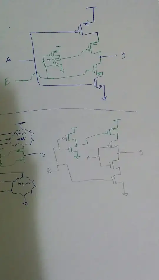
 enter image description here

  • 3
    Please define “better” – Stefan Wyss Oct 24 '18 at 19:23
  • If i knew i would not search for a whole weak. – KilGrave 09 Oct 24 '18 at 19:41
  • Maybe is better in terms of power dissapation .. maybe in terms of size ..i don't really know – KilGrave 09 Oct 24 '18 at 19:42
  • Both works fine but the on the left is used mostly why??? – KilGrave 09 Oct 24 '18 at 19:42
  • 3
    So if you toss a coin 3 times and one time it shows heads and two times it shows tails, why do you think tails should be better? – Stefan Wyss Oct 24 '18 at 19:46
  • 1
    If you don’t know what’s better for your design than I suggest you to reflect over that before choosing the better design. You didn’t put any useful information that would help us to understand what is better – PDuarte Oct 24 '18 at 19:46
  • 1
    is this your actual question? Both works fine but the on the left is used mostly why??? ..... if it is, then why is it not in your post? – jsotola Oct 24 '18 at 19:48
  • draw the full schematic diagrams of the two versions .... maybe the answer will become apparent – jsotola Oct 24 '18 at 19:49
  • I'm assuming that "NW" means "network" but is the network composed of? Telling me an NMOS or PMOS network doesn't explain to me what's inside the network. Also, this is pretty messy. Can you provide a computer-aided drawing? I'm sure there's important things that I cannot see here. –  Oct 24 '18 at 19:53
  • Sorry guys for the confusion. I have edited the post. Is it clear now? – KilGrave 09 Oct 24 '18 at 20:07

1 Answers1

0

The Enable transistors near the output (above) ensure that transitions on A are not coupled to the output. tri-state inverter will be 'better' at tri-stating. The output will be shielded from VDD/GND and the signal.

For the circuit at the bottom, a transient at A can be coupled through parasitic caps to the output.