8

I have little/no experience with pipe networks and have been searching for a methodology to calculate the discharge from multiple outlets of an oil pipe network with a single inlet. As far as i can tell I have too many unknowns to use something like the Hardy Cross method (and often i don't have loops, just multiple branches and outlets as shown below), and Hardy-Cross seems to be used to find flows in pipes with known inflows and outflows, which I don't have.

A good example may be something like this:

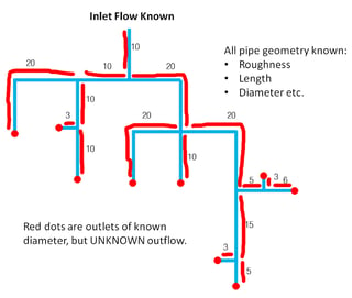
  • Inlet flow rate is known
  • Fluid Properties are known
  • Geometry of all pipes/bends/outlets are known
  • The height above a datum of all pipes and outlets are known
  • Flow is each pipe branch is UNKNOWN
  • Discharge from each outlet is UNKNOWN (ext. pressure can be assumed ambient)
  • I have target outflows, and could modify pipe length/diameters to obtain them

See my very crude diagram: enter image description here

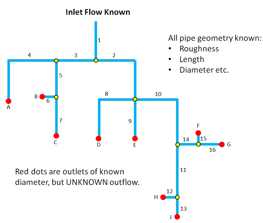
Can anybody suggest an analytical method I can use to calculate the outflows and/or optimise the pipe lengths to obtain a set of target outflows?

A worked example of a similar problem would also be appreciated.

The person who tried to solve this problem before me just divided the inflow up based on the area of the outlets, without considering losses, bends or even the lengths of the pipes anywhere in the network. I have been searching for a while with limited resources for a worked example or solution method for this.

I will probably write a code to solve these problems if I find an appropriate methodology. (I'm aware commercial software does exist that could calculate this, but I don't have access).

Mark
  • 5,333
  • 16
  • 47
Petrichor
  • 518
  • 1
  • 8
  • 22

2 Answers2

5

The flow of current in a circuit is broadly analogous to fluid down a pipe, with the resistance of wires/resistors combining according to standard laws. If you can break your pipe network down into small segments of known "resistance", then you can use current laws, and widely available circuit simulators to get a good approximation of the outlet flow (or at least, much better than your predecessor).

I have taken your diagram, and approximated the lengths of each discrete segment, and given them a relative resistance value. Clearly those segments with corners in might have a higher resistance than a straight of equivalent length - It's up to you to determine the correct values here.

Annotated diagram - lengths approximated to resistances

You can make an equivalent circuit using http://www.falstad.com/circuit/, Screenshot below

screenshot of falstad link in answer

Once your resistances are set, you can adjust the input voltage until you get a nice 'round' current value at the input (e.g. 100mA), and then see the percentage flow at each outlet by reading the current at those points.

You can also add a "Current Source" at any outlets where there is a known flow rate, e.g. provided by some sort of limiting device, and all the other outlets will calculate accordingly.

Jonathan R Swift
  • 7,811
  • 1
  • 16
  • 30
5

You have 9 unknown values you are seeking (the flow at each of 9 outlets), and one that you need to find in the process (the total pressure drop) From the given information, you can assemble equations that you can solve using linear algebra methods.

The sum of the flows at the outlets will equal the inlet flow:

$$Q_t = Q_a + Q_b + Q_c + Q_d + Q_e + Q_f + Q_g + Q_h + Q_j$$

You can also set up equations based on the fact that the pressure drop will be equal along any path from a given node to an outlet.

Pressure drop in any segment can be found using many methods. In this case, the Darcy-Weisbach equation would probably be most useful:

$$h_f = f\cdot\dfrac{L}{D}\cdot\dfrac{v^2}{2g}$$

where:

  • $h_f$ = head loss (m)
  • $f$ = friction factor
  • $L$ = length of pipe work (m)
  • $d$ = inner diameter of pipe work (m)
  • $v$ = velocity of fluid (m/s)
  • $g$ = acceleration due to gravity (m/s²)

Equivalent length information for fittings can be found here: https://www.engineeringtoolbox.com/resistance-equivalent-length-d_192.html

An excel template for using this method can be found here: https://www.engineeringtoolbox.com/equivalent-pipe-length-method-d_804.html

Your example is much more complex than the example given at that page (9 paths vs. 2), but the spreadsheet is scaleable.

Scott B
  • 81
  • 6