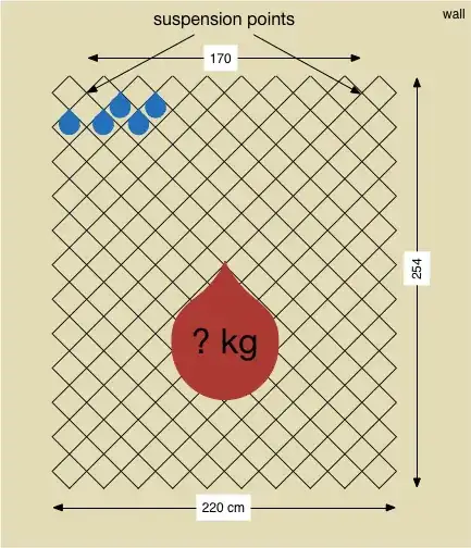
The weld points will definitely be the limiting factor (think about a cargo net, where both the strands and joints are flexible, but usually the strands are straight and the joints are at whatever angle they need to be at to let the strands be straight.)
Since the "shear" strength is listed in linear kN I'm going to assume that that is the effective strength of one joint resisting a force that would slide one bar along the other.
I'll further assume that the steel used has a tensile yield strength of 370 MPa.
I think a good assumption is that the weld joints can be approximated as having a circular cross section. We can estimate the diameter of the cross section:
$$F=\frac{\sigma}2\,\pi\,r^2$$
$$d=\sqrt{\frac{8F}{\sigma\,\pi}}=\sqrt{8\frac{4.4\,\mathrm{kN}}{370\,\mathrm{MPa}\,\pi}}=5.5\,\mathrm{mm}$$
Well, that's unreasonable...so either those welds are made of some super alloy, or the maximum shear load of those welds is less than 4.4 kN.
Edit:( Actually according to this answer the welds can be significantly larger than the wires so this might not actually be unreasonable. )
In fact the maximum tensile load a 4 mm diameter cylinder of 1018 steel could hold before yielding is about 4.4 kN.
So let's proceed as if the diameter of the weld is 1 mm. Each joint could then handle some torque $\tau$ according to:
$$\tau=\frac{\pi\,\sigma_y\,d^3}{24} \approx 50 \,\mathrm{N\cdot mm}$$
There are approximately 250 joints so the maximum total torque is approximately 62 N·m.
The torque produced by the weight be calculated via Virtual Work:
The elongation of a ridged mesh $\epsilon$ is approximately half the radians of deformation $\gamma$.
The gravitational potential energy gained from a uniformly distributed mass by stretching is:
$$E=\frac12 m\,g\,h\,\epsilon= \frac14\,m\,g\,h\,\gamma$$
$$\tau=\frac{dE}{d\gamma}=\frac14\,m\,g\,h$$
Solving for mass gives:
$$m=250\frac{4\,\tau}{g\,h}\approx 2\,\mathrm{kg}$$
This indicates that if the strength of the welds is close to 1018 Steel, and the weld diameter is close to 1 mm then it wouldn't even come close to holding up its own weight (8 kg) when hung at a 45 degree angle. However, if the weld points are 2 mm in diameter then it could hold 15 kg allowing it to support its own weight with a safety factor of 2.
If this were my project I would do destructive testing on one weld joint to see how much torque it takes to yield it. That would allow you to plug in for $\tau$ and get a reasonable estimate for the maximum load.
 .
.